S3.5 Using enthalpy method to deal with phase change difficulties
Up to this point we have covered many aspects of modeling on laser machining. We have presented a general model in previous section along with suitable boundary conditions and initial conditions. But in reality there is an important issue to solve before the model can be said to be able to simulate practical situation. This issue is the intense phase change accompanying any laser machining processes.
The general governing equations can be applied to single phase mediums directly, such as one hundred percent liquid or one hundred percent solid. Heat transfer without phase change is relatively easy to deal with. But laser machining is featured with intense phase changes from solid to liquid, from liquid to solid, from liquid to vapor, or even directly from solid to vapor. Further more the solid-liquid interface is changing violently considering the usually very short laser-material interaction time. Under such circumstances, the numerical computation should take special considerations on the boundary condition.
A large number of numerical techniques are available for the solution of moving boundary problems, the majority of these techniques are concerned with phase change in which conduction is the principal mechanism of heat transfer [Crank]. As mentioned before, in laser machining the solid-liquid interface is changing and confection effect may also be important. Temperature formulation and deforming grids have been used [Ramanchandran et al., Gadgil and Gobin, etc.] to treat the moving liquid-solid interface.
In this section we introduce you to the enthalpy method to deal with this problem. When enthalpy formulations are used, no explicit conditions on the heat flow at the liquid-solid interface need to be accounted for, and a fixed grid numerical modeling can be realized. Further more, the physical details in phase change can be incorporated into the model. For example, the material may melt in a temperature region rather than at a fixed temperature, etc. How to deal with this situation? Enthalpy method is a good choice.
It is really difficult to jump 10 floors in one jump, but surely you can climb to a height more than ten floors if you find the stairs. Let's follow the tradition and divide the difficulties into steps.
Step 1: Definition of Enthalpy and Mushy Region Problem
Definition of Enthalpy
The sum of sensible heat, h, is defined as
![]()
where href is the reference enthalpy, Tref is the reference temperature, cp is specific heat at constant pressure. If one selects href=0, Tref=0, cp to be independent of temperature, then:
![]()
The enthalpy, H, is therefore
H = h + D H
where D H is the latent heat content.
Definition of Mushy Region Problem:
Most convection-diffusion phase change numerical problems assume isothermal phase changes. This is only true for pure materials. However, if the material under consideration is not pure, such as metallurgical alloy, phase changes happen over a temperature region, say Tl ³ T³ Ts . The latent heat becomes a function of the temperature, D H=f(T), as opposed to the step change associated with isothermal phase change. Problems of this type are referred to as Mushy Region Problems. Mushy means the solid plus liquid state in the phase change range.
The latent heat content may vary between zero (solid) and L (liquid), the latent heat of material. The liquid fraction b is defined as
![]() , if T < Ts
, the material is totally solid
, if T < Ts
, the material is totally solid
![]() , if T > Tl ,
the material is totally liquid
, if T > Tl ,
the material is totally liquid
![]() , if Ts <
T < Tl, the material is within the Mushy Region.
, if Ts <
T < Tl, the material is within the Mushy Region.
Now the latent heat is related with temperature and liquid fraction, note that we have assumed a linear relation between liquid fraction and temperature. More general relations between liquid fraction and temperature can be used.
Next concern is the treatment of mushy solidification.
Step 2: Treatment of mushy solidification
To develop a general methodology, one can think the whole computation domain is consisted of porous medium, where the porosity, l = 1 - b , is 1 in the liquid phase, 0 in the solid phase, and is less than 1 in the mushy region. In this way, there is no need to distinguish solid, liquid or mushy phase.
The governing equations are written in ensemble-average velocity, u, which is related to the actual fluid velocity uactual:
u = l uactual
If the flow in the mushy region is governed by the Darcy law, then:
![]()
where K is the permeability, a function of porosity, P is pressure and m is viscosity.
With these preparations, we can write the governing equations.
Step 3: Governing equations
Continuity equation:
![]()
Momentum equation:
![]() , j=1, 2, 3.
, j=1, 2, 3.
![]()
where Fj is the source term of the momentum equation, and g is the gravity acceleration. A is defined as:
![]()
where the porosity l = 1 - b as defined before, C is dependent on the morphorlogy of the poros media, a typical value is 1.5e3. C is chosen small enough to allow for significant flow in the mushy region at the local solid fraction whereas as the limiting value of A is large enough to suppress the fluid velocities in the solid.
Energy equation:
![]()
where r = density, ui = fluid velocity, xi = Cartesian coordinate directions
k = thermal conductivity.
S is the source term in energy equation:
![]()
The value of D H depends on temperature and then on liquid fraction, D H in turn, changes the temperature through energy equation. Iterations are used to compute T and D H.
These three general equations can be applied to any coordinate system and 3D cases.
Further simplification can be made if we assume axisymmetric cylindrical coordinate system. And we can assume viscous force and all body forces can be neglected, then we get the Euler momentum equation.
If we neglect the influence of velocity field in the energy equation, we need only the energy equation, convection and diffusion term varnish. But if we consider the influence of convection and diffusion heat transfer, all three equations are needed.
Step 4: Numerical solutions
The motion is driven by pressure gradient, body force and buoyancy force. On the free surface we have the force balance as discussed before. Other suitable boundary conditions and initial condition can be written down according to special applications. Convection and diffusion have been considered in the energy equation. We already have a system of equations, then we can write them in the general transport equations as discussed in last section. Next one need to discrete the formulae, all equations can be written in a similar form:
![]()
where Ap is the coefficient of point p, Anb is the neighbour point coefficient, S is the source term. The equations can be solved using algorithms such as Simple or Simpler algorithm [Partankar].
The basic idea is:
Starting from initial values, compute pressure field
Solve for velocity field
Solve energy equation
The process of finding pressure field applied Continuity Equation, so that the result velocity field always satisfies continuity equation. TDMA algorithm is used for solving all the implicit difference equations.
Step 5: Example-- An axisymmetric model considering phase changes
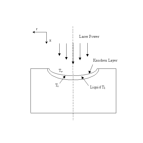
Under the irradiation of a laser beam, target material is first heated from room temperature to melting temperature at which point melting takes place. Depending on laser intensity and material properties, the molten part of material will be evaporated by additional heating when it reaches the vaporization point and a vapor-filled cavity is formed. A thin, so-called Knudsen layer exists at the melt-vapor interface, where the state variables undergo discontinuous changes across the layer. When the incident laser intensity exceeds a certain threshold, vaporization leads to plasma formation, which will absorb a certain percentage of laser energy. The more the intensity goes beyond the threshold, the denser the plasma, and the more percentage of absorption.

Figure 3.59 An axisymmetric model considering phase changes
Neglecting the fluid motion in the cavity, for axisymmetric conditions, the governing equation for energy balance can be written as
![]()
where a is heat diffusivity and r is density, x and r are distances along axial and radial directions as shown in Fig. 3.59.
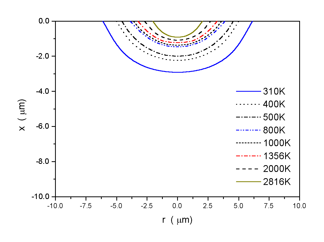
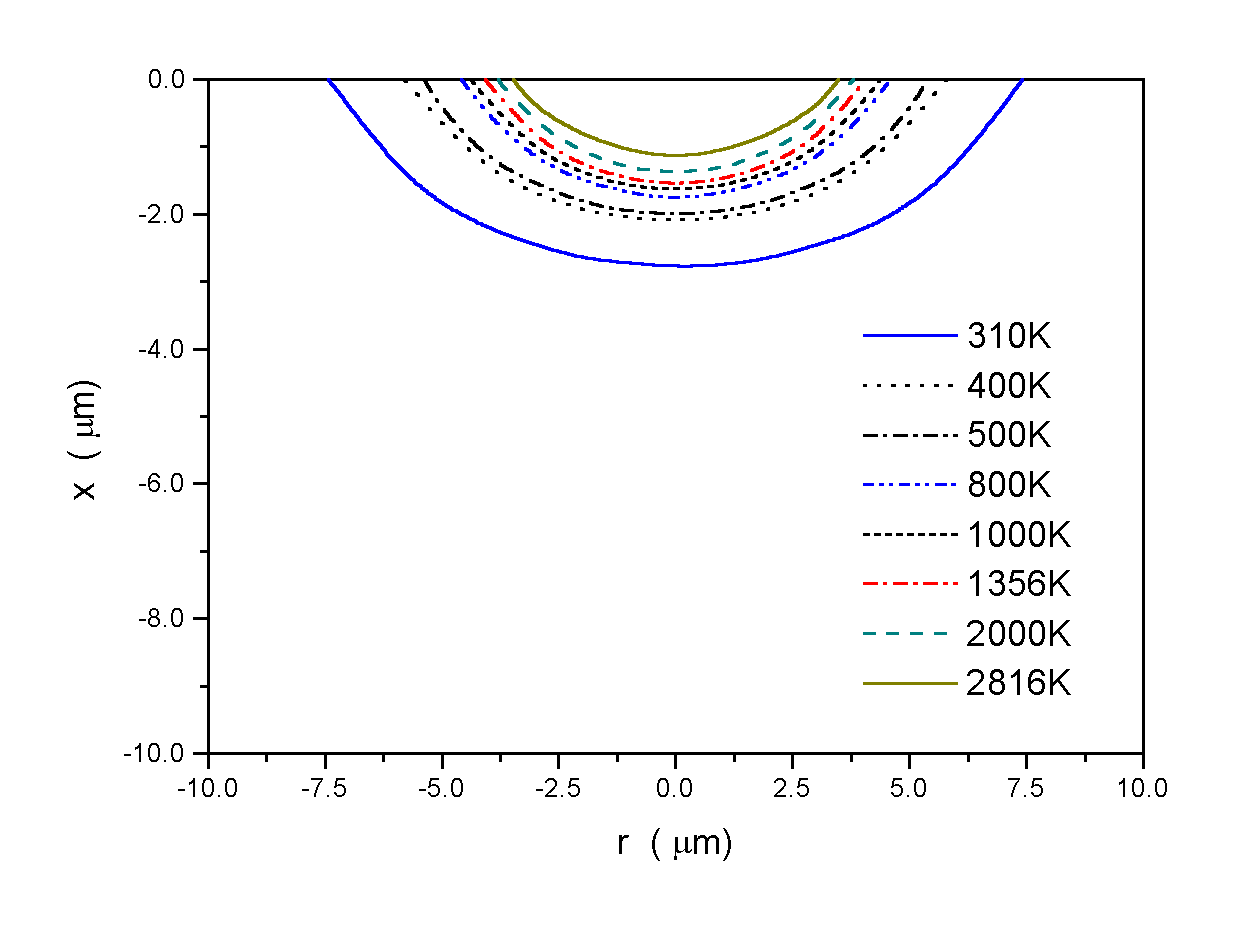
When suitable boundary conditions are applied, the energy equation and the porosity-temperature-enthalpy relations are solved. Two temperature contours are presented below. From the temperature data, the liquid surface profile and surface recess velocity can be calculated.

(a)

(b)
Figure 3.60 Temperature contours at the end of a 50 ns laser pulse (a) I = 6´ 108 W/cm2; and (b) I = 1.5´ 109 W/cm2. (Wavelength l = 355 nm, Gaussian beam, beam radius b = 2.25 m m, Cu) (Wenwu Zhang, et al., 2000)
Comments:
The difficulties at the solid-liquid interface have been overcome. Next we will take a look at the liquid-vapor interface. The liquid-vapor interface provides the important and complex boundary conditions for modeling of laser machining.
References:
J. Crank, Free and moving boundary problems. Clarendon Press, Oxford (1984)
N. Ramachandran, J. R. Gupta and Y. Jalunu, Theraml and fluid flow effects during solidification in a rectangular cavity. Int. J. Heat Mass Transfer 25, 187-194 (1982)
A. Gadgil and D. Gobin, Analysis of two dimensional melting in rectanguar enclosures in presence of convection, J. Heat Transfer 106, 20-26 (1984)
S. V. Partankar, Numerical Heat Transfer and Fluid Flow, Hemisphere, Washington, DC (1980)
V. R. Vollwe and C. Praksh, A fixed grid numerical modeling methodology for convection-diffusion mushy region phase-change problems. Int. J. Heat Mass Transfer., vol. 30, No. 8, pp.1709-1719, (1987).
Wenwu Zhang,Y. Lawrence Yao and Kai Chen, 2000, "Modeling and Analysis of UV Laser Micro-machining of Copper," ICALEO 2000.